Engineer:Michelle Zhou Tel:+86 18795636361 E-mail: michelle.zhou@email.acrel.cn
Jiangsu Acrel Electrical MFG Co. Ltd
1. General Provision
1.1 This specification is formulated to standardize the configuration design of measuring devices in hydroelectric power plants, ensure the long-term, safe and stable operation of hydroelectric power plants, and improve the overall comprehensive economic benefits of hydroelectric power plants.
1.2 This specification is applicable to the configuration design of measuring devices for newly built, rebuilt and expanded hydroelectric power plants.
1.3 The configuration design of measuring devices in hydroelectric power plants should actively adopt new technologies and products that have passed the appraisal.
1.4 The configuration and design of measuring devices in hydroelectric power plants should meet the requirements of the power system for the amount of information collected at the power station and the method of information collection.
1.5 The configuration design of measuring devices in hydroelectric power plants shall not only conform to this code, but also comply with the current relevant national standards.
2. Terminology
2.1 Electrical measuring
Measurement of electrical real-time parameters by means of electricity.
2.2 Energy metering
Measurement of electric energy parameters.
2.3 General electrical measuring meter
Hydroelectric power plants often use pointer meter, digital meter and so on.
2.4 Pointer-type meter
According to the relationship between the pointer and the scale to indicate the measured value of the meter.
2.5 Digital-type meter
In the display can use digital directly show the measured value of the meter.
2.6 Watt-hour meter
An instrument that measures active and/or reactive electrical energy data.
2.7 Intelligent AC sampling device
AC frequency power sampling, directly to the data processing unit for processing to get the voltage, current, active power, reactive power, power factor, frequency, active power, reactive power and other parameters, and through the standard communication interface output multi-functional intelligent meter.
2.8 Transducer
Be measured by the conversion of DC current, DC voltage or digital signal device.
2.9 Measuring instrument accuracy class
Measuring instruments and/or accessories to meet certain measurement requirements designed to ensure that the permissible error and change extremely within the specified limits of the level.
2.10 Automation components
Components and/or devices for condition data monitoring, action execution in hydroelectric plants.
2.11 Non-electricity measuring
Measurement of temperature, pressure, speed, displacement, flow, level, vibration, pendulum and other non-electricity real-time parameters.
3. Electrical measurement and power measurement
Electrical measurement objects include hydro generator/generator motor, main transformer, line, bus, plant transformer, DC system and so on.Figure 1 is a schematic diagram of the electrical wiring of the hydroelectric power plant, showing the electrical wiring of the hydroelectric generator set, main transformer, line, and plant power transformer.
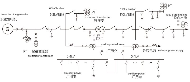
Fig. 1 Schematic diagram of electrical wiring of a hydroelectric power plant
3.1 Electrical measurement and electric energy metering of hydroelectric generator/generator motor.
3.1.2 The static variable frequency starting device of the generator motor should measure the following items.
3.1.3 The hydro-generator/generating motor shall measure the active and reactive electric energy. A hydro-generator that may be operated in phase modulation should measure bidirectional active power; a hydro-generator that may be phase-advanced should be measured in bidirectional reactive power; a generator motor should be measured in bidirectional active power and bidirectional reactive power.
3.1.4 For hydro-generators that may be operated in phase modulation, the active power in both directions shall be measured; for hydro-generators that may be operated in phase advance, the power in both directions shall be measured.Generator motors should measure active power and reactive power in both directions.
3.1.5 When measuring the active power angle of the power system, the power angle of the generator should be measured .
3.1.6 The high voltage side of the excitation transformer should measure the three-phase current, active power and reactive power.
The monitoring configuration of hydro-generator and excitation transformer is shown in Fig. 2, and the equipment selection is shown in Fig. 1.
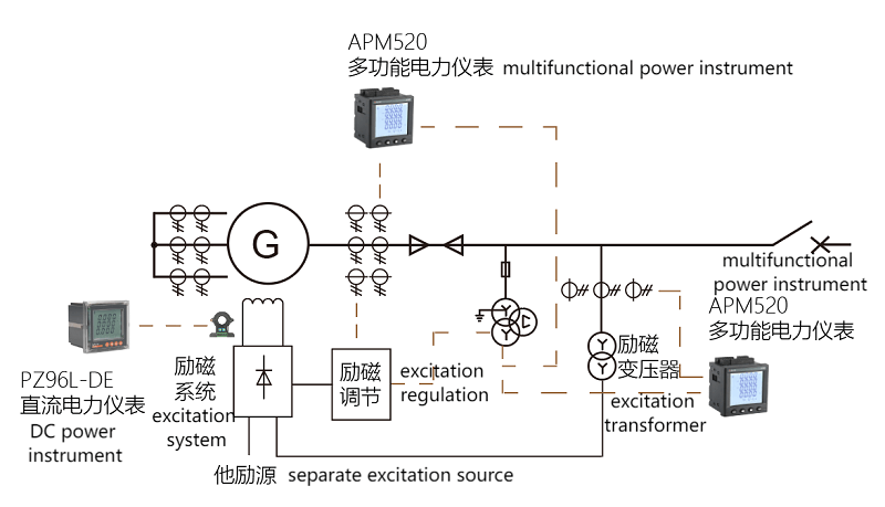
Fig. 2 Electrical measurement configuration of hydro-generator
Model | Function & Application |
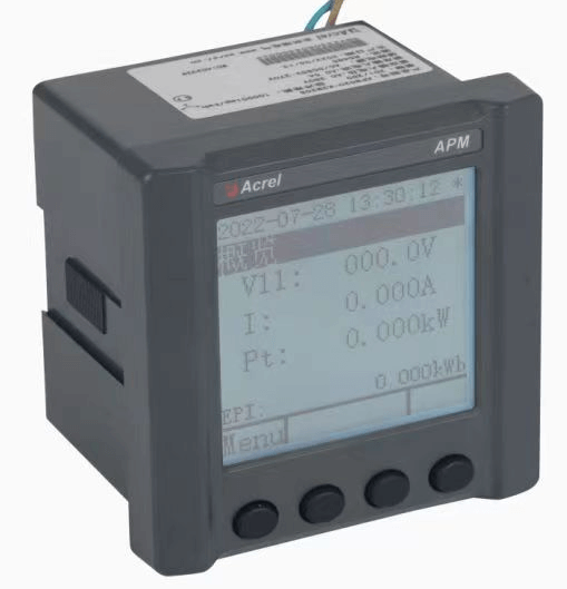
APM520 AC Multifunction Energy Meter | Three-phase current, line voltage/three-phase phase voltage, two-way active / reactive power, two-way active/reactive energy, power factor, frequency, harmonic distortion rate, voltage pass rate statistics, RS485/Modbus-RTU interface Applied in electrical monitoring of generators and excitation transformers |
PZ96L-DE DC Energy Meter | Measure the excitation voltage, excitation current, etc. in the excitation system, and it is equipped with Hall sensors. Applied in excitation current, voltage measurement |
DJSF1352-RN DC Energy Meter | |
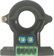
AHKC-EKAA Hall Sensor | Measure DC0~(5-500)A current, output DC4-20mA, and work with DC12/24V power supply. Applied in excitation current sensor |
Table 1 Monitoring selection of hydro-generator and excitation transformer
3.2 Electrical measurement and electric energy metering of boosting and sending system
3.2.1 Main transformer measurement and power metering items shall meet the following requirements :
1) Double-winding transformers should measure the three-phase current, active power, and reactive power on the high-voltage side, and one side of the transformer should measure active energy and reactive energy.
2) Three-winding transformers or auto transformers should measure three-side three-phase current, active power, and reactive power, and should measure active energy and reactive energy on three sides. The auto transformer common winding should measure the three-phase current.
3) When the generating unit is wired as a unit but the generator has a circuit breaker, the low voltage side line voltage and three-phase voltage should be measured..
4) Active power and reactive power should be measured on both sides of the contact transformer, and active energy and reactive energy should be measured.
5) When it is possible to transmit and receive power, the active power in both directions should be measured and the active energy in both directions should be measured; when it is possible to run in phase lag and phase advance, the reactive power in both directions should be measured and the reactive energy in both directions should be measured.
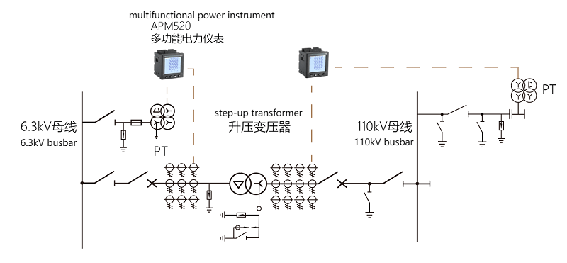
Fig. 3 Electrical measurement configuration of main transformer in hydroelectric power plant
Item | Function & Application |
APM520 AC Multifunction Energy Meter | Three-phase current, line voltage/three-phase phase voltage, two-way active/reactive power, two-way active/reactive energy, power factor, frequency, harmonic distortion rate, voltage pass rate statistics, RS485/Modbus-RTU interface Applied in main transformer high and low voltage side measurement |
Table 2 Selection of main transformer monitoring
3.2.2 Line measurement items shall meet the following requirements:
1) 6.3kV ~ 66kV lines should measure single-phase current, and when conditions permit, two-phase current or three-phase current can be measured.
2) 35kV and 66kV lines should measure active power, and 6.3kV ~ 66kV lines can also measure active power and reactive power when conditions permit .
3) 110kV and above lines should measure three-phase current, active power and reactive power.
4) 6.3kV and above lines should measure active energy and reactive energy.
5) When the line is likely to transmit and receive power, the active power in both directions should be measured and the active energy in both directions should be measured.
6) When the line may run with a phase lag or a phase advance, the reactive power in both directions should be measured and the reactive energy in both directions should be measured.
7) When required by the power system, the power angle of the line should be measured for the line of the step-up station.
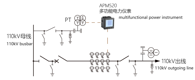
Fig. 4 Electrical measurement configuration for hydroelectric power plant lines
Item | Function & Application |
APM520 AC Multifunction Energy Meter
| Three-phase current, line voltage/three-phase phase voltage, two-way active/reactive power, two-way active/reactive energy, power factor, frequency, harmonic distortion rate, voltage pass rate statistics, RS485/Modbus-RTU interface Applied in 6.3kV~110kV line measurement |
Table 3 Line measurement selection
3.2.3 Bus bar measurement items shall meet the following requirements:
1) 6.3kV and above generator voltage busbars and 35kV , 66kV busbars should measure the busbar voltage and frequency, and measure the three-phase voltage at the same time.
2) 110kV and above buses should measure three line voltages and frequencies.
3) 6.3kV and above bus tie circuit breakers, bus section circuit breakers, inner bridge circuit breakers, and outer bridge circuit breakers should measure AC current, and 110kV and above should measure three-phase current.
4) Three-phase current should be measured for each circuit breaker circuit of 3/2 wiring, 4/3 wiring and corner wiring.
5) Bypass circuit breakers, bus tie or section and bypass circuit breakers, and 35kV and above outer bridge circuit breakers should measure active power and reactive power, and measure active energy and reactive energy.When it is possible to transmit and receive power, the active power in both directions should be measured and the active energy in both directions should be measured; in the case of phase lag and phase advance operation, the reactive power in both directions should be measured and the reactive energy in both directions should be measured.
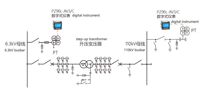
Fig. 5 Electrical measurement configuration of busbar in hydroelectric power plant
Item | Function & Application |
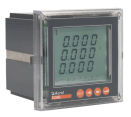
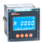
PZ96L-AV3/C AC Panel Voltage Meter | Measure three-phase voltage, line voltage, RS485/Modbus-RTU interface. Bus voltage measurement, local display Applied in bus voltage measurement, local display |
Table 4 Bus measurement selection
3.2.4 Three-phase current and reactive power should be measured for 110kV and above shunt reactor groups, and reactive energy should be measured. 6.3kV ~ 66kV shunt reactor circuit should measure AC current.
Item | Function & Application |
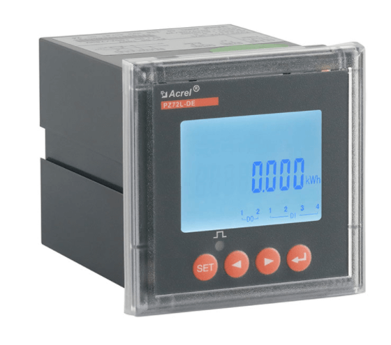
PZ96L-E3/C AC Panel Energy Meter | Measure three-phase current, active/reactive power, active and reactive energy, RS485/Modbus-RTU interface. Applied in reactor measurement, local display |
Table 5 Reactor measurement selection
3.3 Electrical measurement and energy metering of plant power system
3.3.1 AC current, active power and active energy should be measured on the high-voltage side of the factory power transformer. When the high-voltage side does not have the measurement conditions, it can be measured on the low-pressure side.
3.3.2 AC voltage should be measured for the working busbar of factory electricity. When the neutral point is not effectively grounded, a
Line-to-line and three-phase voltages; when the neutral is effectively grounded, three line-to-line voltages shall be measured.
3.3.3 Three-phase current should be measured for power supply lines in the factory area, and active energy can be measured according to the needs of electric energy measurement.
3.3.4 The three-phase current should be measured for 50kVA and above utility power transformers with lighting loads.
3.3.5 The single-phase current should be measured at least for the motor circuit of 55kW and above .
3.3.6 When the low-voltage side of the factory power transformer is a 0.4kV three-phase four-wire system, the three-phase current should be measured.
3.3.7 The section circuit breaker for factory power shall measure single-phase current.
3.3.8 Diesel generators should measure three-phase current, three-phase voltage, active power and measure active energy.
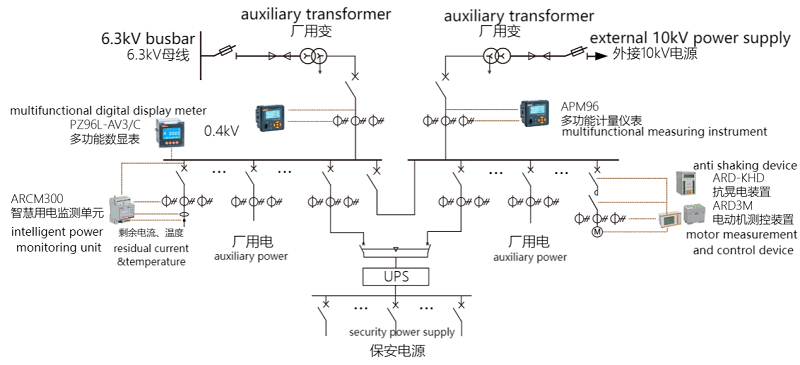
Fig. 6 Electrical measurement configuration of utility power system of hydroelectric power plant
Item | Function & Application |
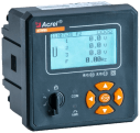
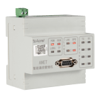
AEM96 Multifunctional energy meter | Three-phase current, line voltage/three-phase phase voltage, active/reactive power, active/reactive energy, power factor, frequency, harmonic distortion rate, RS485/Modbus-RTU interface. Applied in energy metering and monitoring |
PZ96L-AV3/C Digital instrument | Measure three-phase voltage, line voltage, RS485/Modbus-RTU interface. Applied in bus voltage measurement |
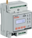
ARCM300 Smart electricity monitoring unit | Three-phase current , line voltage/three-phase phase voltage , active / reactive power , active/reactive energy, power factor , frequency, residual current, 4-way temperature, RS485/Modbus-RTU interface. Applied in feeder measurement |
ARD3M Motor measurement and control device | Suitable for low-voltage motor circuits with rated voltage up to 660V, integrating protection, measurement, control, communication, operation and maintenance (over/under current), voltage (over/under voltage) phase failure, locked rotor, short circuit, leakage, three-phase unbalance, overheating, grounding, bearing wear, stator and rotor eccentricity, and winding aging to give an alarm or protection control. Applied in motor measurement and control |
ARD-KHD Anti-shaking device | Prevent the contactor from tripping when the voltage is temporarily lost, and run uninterruptedly after the voltage is restored to avoid the system from being impacted. Applied in motor measurement and control |
Table 6 Selection of Electrical Measurement Configuration for Plant Power System
3.4 Electrical measurement of DC power system
3.4.1 The DC power supply system shall measure the following items:
1) DC system bus voltage without step-down device.
2) DC system closing bus voltage and control bus voltage with step-down device.
3) The charging device outputs voltage and current.
4) Battery pack voltage and current.
3.4.2 The battery circuit should measure the floating charge current.
3.4.3 When a fixed valve-regulated lead-acid battery is used, it is advisable to measure the voltage of a single battery or an assembled battery by means of inspection.
3.4.4 DC distribution cabinet should measure the bus voltage.
3.4.5 The DC bus insulation test shall comply with the relevant provisions of the current industry standard "Code for Design of DC Power Supply System in Hydroelectric power Plants" NB/T 10606.
3.4.6 When the DC power system is equipped with a microcomputer monitoring device, the measurement of conventional instruments can only measure the DC bus voltage and battery voltage.
3.5 Uninterruptible Power System (UPS) Electrical Measurements
3.5.1 UPS should measure the following items :
1) Output voltage.
2) Output frequency.
3) Output power or current.
3.5.2 UPS main distribution cabinet should measure incoming current, bus voltage and frequency.
3.5.3 The UPS distribution cabinet can measure the bus voltage.
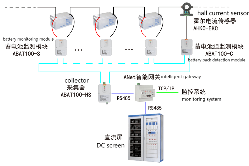
Figure 7 DC system and battery electrical measurement
Item | Function |
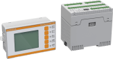
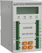
ABAT100-HS Data Collector | It can monitor up to 120 batteries, group voltage overcharge/discharge, single voltage overcharge/discharge, current overcharge/discharge, single internal resistance too high, abnormal communication, etc., with overvoltage and short circuit protection, RS485/Modbus- RTU interface Applied in battery monitoring module data acquisition |
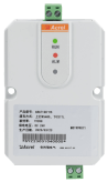
ABAT100-S Battery Monitoring Module | On-line monitoring of the voltage, internal resistance and negative electrode temperature of each backup battery Applied in battery monitoring module |
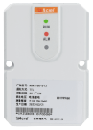
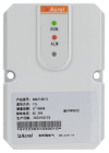
ABAT100-C Battery Pack Monitoring Module | Monitor the charging and discharging current and ambient temperature of a group of batteries Applied in battery pack monitoring module |
AHKC-EKC Hall Sensor | Measure DC0~(500-1500)A current, output ±5V. Applied in DC current monitoring |
ANet-2E4SM Smart Gateway | Edge computing gateway, embedded linux system, provides security requirements such as AES encryption and MD5 identity authentication, supports breakpoint resume, supports Modbus, ModbusTCP, DL/T645-1997, DL/T645-2007, 101, 103, 104 protocols Applied in data acquisition, conversion and logic judgment |
3.6 Commonly measured electrical measuring instruments and electric energy measuring instruments
3. 6.1 The setting of electrical measuring instruments shall meet the following requirements:
1 The settings of the electrical measuring instruments for routine testing should be able to correctly reflect the operating parameters of the electrical installations.
2 When there is a requirement for remote transmission function, an electrical measuring instrument that transmits electrical parameters by means of data communication or analog output shall be configured.
3 Hydraulic generators, generator motors, double-winding main transformer high-voltage side, three-winding main transformer high-voltage side, medium-voltage side and low-voltage side, can replace the section of the line circuit breaker and the bus-tie circuit breaker, the outer bridge circuit breaker, Angle-connected circuit breakers and lines should be equipped with comprehensive measuring instruments for AC sampling electricity; factory power transformers and power distribution circuits of factory power systems can be equipped with comprehensive measuring instruments for AC sampling.
3.6.2 The settings of the analog screen’s regular measuring instruments should meet the following requirements:
1 When the computer monitoring system does not have an analog screen, the control room should cancel the routine measuring instruments. When the computer monitoring system is equipped with an analog screen, the frequently measured instruments on the analog screen should be simplified, and computer-driven digital instruments can be used.
2 The following electrical measuring instruments should be installed on the simulation screen:
1 ) Active power meters and reactive power meters of hydroelectric generators and generator motors.
2 ) Active power meters and reactive power meters for lines with a voltage of 110kV and above ; active power meters for lines with a voltage of 35kV and above and below 110kV.
3 ) Line voltmeter and frequency meter for 35kV and above buses.
4 ) Total active power meter and total reactive power meter of the whole plant.
5 ) Two-way reactive power meters or active power meters installed on hydro-generators that may run in phase advance or phase modulation; two-way active power meters and reactive power meters are installed on generator motors and lines that may transmit and receive electricity. power meter.
6 ) Other measuring instruments.
4. Conclusion
The configuration of the measuring instruments of the hydroelectric power station and the design purpose of the power management system of the plant are all aimed at meeting the needs of the safe and economical operation of the hydroelectric power plant and the commercial operation of electric power, ensuring accuracy and reliability, advanced technology, convenient monitoring, and economical application.
References:
[1] Acrel Enterprise Microgrid Design and Application Manual. Version 2022.05
 English
 日本語
日本語 한국어
한국어 français
 Deutsch
 Español
 italiano
 русский
 português
 العربية
 tiếng việt
 Türkçe